High power HF and ALE Solutions
Marine, Ground to Air & Military Broadcast Communication Solutions
|
• 2, 5, 10 & 20kW and ALE Project Systems
The Barrett High power amplifiers are natively integrated with the Barrett 4050 HF SDR Transceiver/Exciter |
|


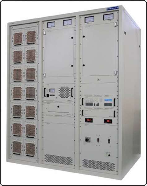
 2kW Amplifier System
10kW system Block diagram
Barrett 2,5,10,15,& 20KW High Power systems are designed to be general-purpose, high performance and fully Solid-state HF transmitters providing continuous output power.
The Transmitter allows presetting of up to 100 frequencies in the range from 1.5MHz to 30MHz.
Operating modes are J3E (USB LSB,) - H2B (AM) - J2A (CW) – CF (Custom Filter) -ISB (data option) plus many more with use of paired external modems.
The Transmitter is designed in compliance with relevant CCIR recommendations, and ITU radio regulations, ensuring high reliability and Easy of operation/maintenance.
It is equipped with circuit’s elimination hums and noises while compensating distorted waves.
All functions for remote control operation are built-in. Therefore, if software installed in PC remote control operation is possible by RS-232 or RS-422/485 and TCP/IP interface.
This Transmitter composition of RF Stage designed is HF SSB Exciter, RF Driver Amplifier Unit and Solid State Power Amplifier Modules. Power Amplifiers are designed 1KW Power Output Module x X Modules Combination to meet system power requirements.
Each unit has individual protection circuits and is designed for simple maintenance. System LEDs indicate operation performance and conditions (green for normal condition and red for abnormal condition).
It has smoke and over-temperature sensors, which make power-off automatically if they sense such environment.
It has surge protection against over-voltage and over-current.
Output efficiency monitoring and protection functions are built in to avoid malfunction from operator error.
 |  |
General Specifications | |||
| Frequency Range | 1.5 ~ 30 MHz | Temperature | Ambient 0 to 50C |
| Power Output PEP Voice and CW | 2, 5, 10, 15 & 20kW ±1dB | Humidity | 95% relative, non- condensing |
| Harmonics & Spurious | Less than -60 dB | Altitude | 3000 m above sea level (not airborne), 9000 m transportation |
| Output Impedance | 50Ω | Output VSWR protection | 3:1 nominal all magnitude and phases |
| Output Connector | 1-5/8” EIA Flange | Thermal Overload protection | 85°C |
| MTBF | 10000 Hours (Estimated) | Fault Log | System events and error reporting |
| MTTR | 60 Mins | Input Power | 3Phase 380V-485V, 50/60 Hz |
| Power Requirements | 220V / 380V ± 10% 50Hz/60Hz 3 Phase | Typical Rack Configuration | 2kW - 1 Rack, 5kW - 2 Racks, 10, 15 & 20kW - 3 Racks |
| Cooling Forces | AIR(FAN Motor) | Construction | Modular racked assemblies for simple access servicing. |
Transmitter Specifications | |
| Harmonic Suppression | Better than 60dB below carrier |
| Intermodulation Distortion | Better than 36dB below PEP |
| Carrier Suppression | Better than 70dB below PEP |
| Undesired Side Band | Better than 70dB below PEP |
| Undesired Side Band | In Band Noise Better than 50dB below PEP |
Specifications are typical to custom project solutions. Equipment descriptions and specifications are subject to change without notice or obligation.