AT MGSS Mobile Ground Surveillance System
| AT MGSS Features | AT MGSS Applications |
|
|
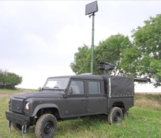
The AT MGSS Mobile Ground Surveillance System offers a unique cost-efficient defence solution providing an increased capability of early threat recognition and improved perimeter control. It is designed for long range security patrols, for controlling large areas and defending mobile targets, and for situations where security demands an on-going adaptation of reconnaissance patterns – the operators of an AT MGSS will be able to quickly redefine the boundaries of the controlled area to instantly react to any situation that may arise.
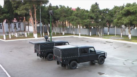
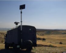
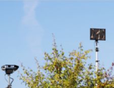
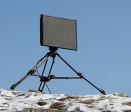
The AT MGSS is an engineered and configured vehicle equipped with a number of surveillance modules – an AT PGSR Portable Ground Surveillance radar unit, an optional AT PSR Perimeter Security Radar, an electro optical sensor array and a Command Centre. The electro-optical head is mounted on a retractable mast protruding from the roof of the vehicle. The AT PGSR radar unit is also mounted on a retractable electro-hydraulic mast assembly. The optional AT PSR radar unit is not mounted on the vehicle, it can be deployed as a stand-alone unit within the vehicle’s range and be under control of the Command Centre which is set up in the vehicle cabin.
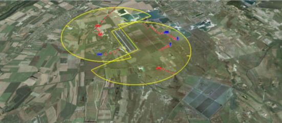
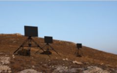
During surveillance sessions, remote AT PSR radar units are deployed to oversee the secured area with complementary surveillance angles. The operating platform and our unique Adaptive Multi-sensor Systems, presents an easy to operate user interface, offering the possibility of multi-tasking and educated decision-making to the operator. If any of the radar units alerts the operator of a threat or intrusion, the operator can use the Electro-Optical Sensor Array to get a visual image of the threat, thereby improving his chances to take proper measures. The operators control all subordinate sensor units from inside the vehicle, via a common interface – surveillance data from all instruments is displayed on the same operator platform.
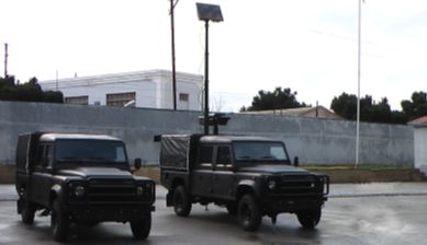
The operating system also allows the AT MGSS to function in automatic mode, in a non-interrupted mode of operation. The sensor modules can be set to respond to each other’s signals in order to present the operator with an optimum selection of data for further analysis.
Via the Command Centre node, the AT MGSS system can also control other independently deployed stand-alone units which are configured with proper access. The AT MGSS can also be integrated within a larger network hierarchy of command nodes for operations of a greater scale.
 |  |
AT MGSS Mobile Ground Surveillance System – Specifications
Overall Hardware Setup and Characteristics
| Instrumentation | AT PGSR radar unit AT PSR radar unit (optional) Electro-Optical Sensor Array Command Center node Other instruments as needed |
| Auxiliary Equipment | GPS and North Finding Device Other equipment as needed |
| Vehicle Options | Any vehicle as needed subject to technical |
| Power Supply | Optional power generator (12 and 24V DC, 230V AC) – unlimited operation period Vehicle-built-in battery set (12 and 24V DC) |
| Temperature Ranges | Operation: -32°C to +50°C Storage: -40°C to +60°C |
| MTBF | > 10 000 hr (not including vehicle specific failures) |
AT PGSR Vehicle-mounted Ground Surveillance Radar Unit
| Typical Detection Ranges | Pedestrian: 6 km (RCS 0.5 m2) Armed soldier: 8 km (RCS 1 m2) Vehicle: 15 km (RCS 10 m2) Large vehicle: 24 km (RCS 50 m2) |
| Scanning Modes | Azimuth Sector Scan (6°–346°) Continuous Rotation Scan (n x 360°) |
| Scan Rate | 7°/sec and 14°/sec, operator selectable |
| Accuracy | Range: ±3 m (at 3 km range) Azimuth: ≤ 0.3° |
| Minimal Detectable Radial Speed | 1.0 km/h |
| Target Capacity | 10 plots/sec over 300 tracks over 1000 displayed plots |
| Target Classification | Automatic and Audio Integrated Acoustical Target Identification |
| Processing | STC, FFT, CFAR, PLOT EXT., TRACK EXT. |
| Data/Control Interface | RS-485, WIFI, Ethernet |
| Installation | Mast-mounted (retractable) |
Electro Optical Sensory Array
Type and manufacture to be tailor-made to customer’s needs, A typical long range configuration is as follows:
| Thermal Imager | Fields of View (FoV): Continuous Zoom 0.6° to 2.9° or 1.1° to 5.5° Detector: 640 x 480 Detection at Mid FoV: 4 km Recognition at Narrow FoV: 5 km |
| Daylight (CCD) Camera | Detector type: CCD ½” Color/BW Resolution: 752 x 582 Signal-to-noise ratio: 62 dB |
| Laser Range Finder | Measuring range: 80 m to 20 km Range resolution: 5 m Multiple targets: 1st and last targets |
| Pan and tilt head | Mounted on mast (fixed or retractable) Variable speed Azimuth range: 360° (Slip ring) Elevation range: ± 50° |
 |  |
